Yes — a HackRF One can detect drones. It tunes from 1 MHz to 6 GHz, covering every band that consumer and FPV drones transmit on, its 20 MHz of instantaneous bandwidth captures a complete digital drone downlink, and its firmware sweep mode scans the full 6 GHz range in roughly 0.75 seconds. The limits are just as real: an 8-bit ADC, no front-end preselection, and a single half-duplex receive channel over USB 2.0. That combination makes it a strong prototyping platform and a poor fielded sensor — this guide covers both halves of that verdict, and the upgrade path between them.
What the HackRF One brings to drone detection
The Great Scott Gadgets documentation sums up the platform in a handful of numbers, and each one has a direct consequence for drone work:
- 1 MHz to 6 GHz tuning, half-duplex. Every drone band of interest — 433/868/915 MHz control, 1.2 GHz analog video, 2.4 and 5.8 GHz control and video — is inside the range. Half-duplex means receive-only operation is fine; it only matters if you imagine the same box doing anything other than listening (which, for legal reasons covered later, you should not).
- 2 to 20 Msps quadrature, 8-bit I and 8-bit Q. Twenty MHz of bandwidth is exactly one OcuSync-class OFDM downlink channel, so you see the whole signal at once. The 8-bit converter behind it (a MAX5864 analog front end, 48.5 dB SINAD at 22 Msps in the manufacturer's datasheet — under eight effective bits) is the defining constraint: a weak drone link sharing spectrum with a strong Wi-Fi burst simply disappears into the converter's quantization noise. Production counter-UAS receivers use 12–16-bit converters for exactly this reason.
- No preselection, −5 dBm maximum input. The wideband front end has no sub-band filtering ahead of it, so a nearby phone or access point desensitizes everything, and a truly strong nearby transmitter can damage the receiver. Front-end filtering is a production feature.
- Hi-Speed USB 2.0. A single HackRF One at 20 Msps uses practically all the bandwidth of one USB 2.0 bus — you cannot hang several off a hub and scale that way. One device per bus is the rule.
- Stock crystal, external clock port. HackRF One ships without a temperature-compensated oscillator (the newer HackRF Pro adds a built-in TCXO). For frequency-accurate work you feed a 10 MHz, 3.3 V square wave into the CLKIN SMA port, or daisy-chain one device's CLKOUT to another's CLKIN.
- Sweep mode in firmware.
hackrf_sweepretunes the radio without host involvement, achieving a sweep rate of 8 GHz per second — 0.75 seconds for the entire 6 GHz tuning range. It interleaves two 5 MHz output slices per 20 MHz step to dodge the center DC spike and band-edge roll-off, at the cost of halving the theoretical rate; a linear mode uses the full 20 MHz of every step but prints a DC spike every 20 MHz.
Two operating notes from the documentation matter in practice. First, sample rates below 8 Msps are not recommended — the baseband filter cannot reject adjacent-spectrum energy cleanly below that. Second, receive gain is distributed across three stages (an ~11 dB RF amplifier, IF gain 0–40 dB in 8 dB steps, baseband gain 0–62 dB in 2 dB steps), and finding the right combination for your site is a manual exercise that directly determines whether weak drone links are above or below your effective noise floor. For a fuller comparison of where HackRF sits among RTL-SDR dongles, USRP devices and purpose-built military receivers, see our guide to SDR platforms for defense.
Which drone emissions a HackRF can realistically detect
Not every drone signal is equally visible, and one common category is genuinely not an SDR problem at all. The table below is the honest version of what a HackRF shows you:
| Drone emission | Band | What the HackRF shows | Verdict |
|---|---|---|---|
| Wi-Fi-based drones (toy, educational, phone-controlled) | 2.4 / 5 GHz 802.11 | Ordinary Wi-Fi bursts — the drone is just another station or access point | Easy to see, hard to attribute |
| Digital control + video links (DJI OcuSync-class) | 2.4 + 5.8 GHz, 20 MHz OFDM channels | A continuous wideband OFDM pair; the AES-encrypted payload does not hide the energy | Detectable across the band |
| Vendor tracking beacon (DJI DroneID-type) | Rides the OFDM downlink, ~640 ms interval | Small periodic frames detached from the video stream | Best identity source if you invest in decoding |
| Analog FPV video | 5.645–5.945 GHz channelized; 1.2/1.3 GHz for long-range | A strong, steady analog video carrier roughly 8 MHz wide | The easiest signal in the sky |
| Long-range RC control (ExpressLRS-class, Crossfire) | 433/868/915 MHz and 2.4 GHz | Narrow, low-duty-cycle frequency hops or LoRa chirps | Needs a wideband channelized watch |
| Remote ID (ASTM F3411) | Bluetooth and Wi-Fi transports | Ordinary BLE / Wi-Fi frames, not a distinctive RF signature | Use a Wi-Fi/BLE receiver instead |
Three of these rows deserve explanation. The OFDM control and video links used by mainstream consumer drones are the core use case: detection does not require decryption, only the presence of a 20 MHz-wide OFDM signal with drone-like timing and duty cycle. DJI advertises around 15 km of line-of-sight range for these links, so the drone is usually radiating far more power than your receiver needs to see it — the constraint is your noise floor, not the drone.
The tracking beacon row is the interesting one. Researchers at Ruhr-Universität Bochum and CISPA (NDSS 2023) reverse-engineered DJI's proprietary DroneID broadcast and showed, first, that it is not encrypted despite widespread belief to the contrary, and second, that it carries the drone's position, the home point, and the remote pilot's location, repeating roughly every 640 ms. Their prototype — a laptop plus a small SDR — decoded it reliably within about 10 m, a range limited by their focus on reverse engineering rather than performance, not by any property of the signal. We deliberately stay at this descriptive level; a production decoding chain is an engineering program of its own.
Remote ID is not an SDR problem. The FAA's Part 89 rule requires registered drones to broadcast identification and position on spectrum compatible with ordinary personal wireless devices, using the Bluetooth and Wi-Fi transports defined in ASTM F3411. A HackRF will show that traffic only as generic ISM energy; a Wi-Fi/Bluetooth-capable receiver — in the limit, a phone — is the right tool. And the standard itself notes it does not address aircraft that deliberately circumvent Remote ID, which is exactly why RF detection of the raw links remains necessary. The architecture around all of these emissions is covered in our companion guide to drone detection with RF.
The detection pipeline: sweep, dwell, classify, alert
A working HackRF prototype is a small pipeline, and each stage has a standard shape:
- Baseline the site first. Before alerting on anything, record what normal occupancy looks like — our drone RF spectrum survey guide covers this in depth. A detector without a baseline either screams at every Wi-Fi burst or sits deaf.
- Sweep wide, then dwell. Run
hackrf_sweepacross the full range (or the 2.4 and 5.8 GHz ISM sub-bands) to find candidate energy, then park at 20 Msps on the active slice to capture the whole channel — hop sequences, burst timing and all. - Detect with an adaptive threshold. Convert IQ to a spectrogram and run a CFAR-style detector that estimates the noise floor per frequency bin and flags exceedances relative to that estimate, never against a fixed absolute power level.
- Extract features. For each detection: center frequency, bandwidth, burst duration, inter-burst period, hop rate and pattern. A frequency-hopping control link reveals itself by the pattern of its hops, not by any single burst.
- Classify. Start with rules (an 8 MHz steady carrier at 5.8 GHz is analog video; paired 20 MHz OFDM blocks with asymmetric burst timing is a consumer control/video link), then graduate to trained models — the techniques are covered in our articles on signal classification with machine learning and SDR signal-processing pipelines.
- Alert with track logic. Require several consistent detections inside a time window before raising an alert, so a single microwave-oven artifact never reaches an operator.
The tooling is deliberately boring: hackrf_sweep emits CSV rows of the form date, time, hz_low, hz_high, hz_bin_width, num_samples, dB, … with bin widths from 5 MHz down to 2445 Hz, which any scripting language consumes:
# sweep the 2.4 GHz ISM band at ~2.4 kHz resolution
hackrf_sweep -f 2400:2483 -w 2445
# date, time, hz_low, hz_high, hz_bin_width, num_samples, dB, dB, ...
Around it, GNU Radio and SDR++ handle the 20 Msps dwell captures, SoapySDR keeps the processing code portable to other receivers, and Python with NumPy is enough for the detector and feature stages on any modern laptop. Host requirements are modest — the documentation specifies no minimum CPU and merely warns that SDR is CPU-intensive and that a HackRF wants effectively the whole USB 2.0 bus to itself at high sample rates.
False alarms: surviving the 2.4 and 5.8 GHz urban clutter
The 2.4 and 5.8 GHz ISM bands are the busiest unlicensed spectrum in existence, and they are exactly where consumer drones live. In an urban deployment your detector competes with hundreds of Wi-Fi networks, Bluetooth traffic, and video senders, and the HackRF's 8-bit ADC makes the problem harder: every strong ISM signal eats converter dynamic range that a weak drone link needs. Three practices keep false alarms survivable. First, per-bin relative thresholds rather than absolute power floors. Second, a maintained rolling baseline so the detector notices deviations from this site's normal occupancy rather than spectrum-wide absolutes. Third, confirmation logic that demands a drone-like pattern — sustained duty cycle, hop structure, paired uplink/downlink — rather than a single energy excursion. The classification stage is where most of the real engineering lives, and it is the same problem whether the front end is a HackRF or a production receiver.
Why one HackRF cannot give you a bearing
A single HackRF One reports frequency, bandwidth and power. It cannot tell you where the emitter is, because direction finding needs either a phase-coherent multi-channel array at one site or several time-synchronized sensors performing TDOA or FDOA fixes. The hardware offers building blocks — a shared 10 MHz clock via CLKIN/CLKOUT, and hardware triggering that the documentation credits with time synchronization accurate to less than one sample period — but the documentation deliberately stops short of promising phase coherence between devices, and a non-coherent TDOA rig built from independent oscillators gives you frequency offset problems before it gives you fixes. The optional Opera Cake antenna switch has a time-mode explicitly intended for experimentation with pseudo-Doppler direction finding, which is a legitimate science-fair-grade bearing experiment and not a production DF capability. Coherent arrays such as five-channel direction-finding receivers exist at the low end of the market and work well — but they cover roughly 100 MHz to 1 GHz, which excludes 2.4 and 5.8 GHz. For real geolocation you need coherent multi-channel SDRs or a networked TDOA/FDOA architecture; the companion articles on FDOA geolocation and our existing coverage of passive TDOA/FDOA techniques cover the geometry.
From HackRF prototype to production sensor
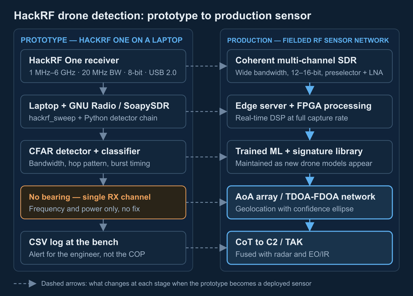
The prototype proves the detection chain. The production system keeps the chain and upgrades every stage of it:
| Capability | HackRF One prototype | Production counter-UAS RF sensor |
|---|---|---|
| Tuning range | 1 MHz–6 GHz | ~70 MHz–6 GHz per channel, band-focused front ends |
| Instantaneous bandwidth | 20 MHz, one channel | 100–400 MHz across two or more coherent channels |
| Dynamic range | 8-bit ADC, 48.5 dB SINAD | 12–16-bit ADCs — tens of dB more usable range |
| Front end | Wideband, no preselection, −5 dBm max input | Preselectors, LNAs, filtered sub-bands, input protection |
| Reference | Stock crystal; optional 10 MHz CLKIN | GPS-disciplined oscillators, calibrated receive chains |
| Geolocation | None — single channel (pseudo-Doppler only as an experiment) | Coherent AoA arrays and/or TDOA-FDOA sensor networks |
| Throughput | USB 2.0, one 20 Msps stream per bus | 10 GbE or FPGA processing at full capture rate |
| Detection logic | hackrf_sweep + open tools + hand-written rules | Maintained signature libraries, trained ML classifiers, track management |
| Environment | Bench enclosure | Ruggedized, EMI-shielded, temperature-rated |
| Output | CSV rows in a terminal | CoT to C2/TAK, fused with radar and EO/IR |
Two rows deserve emphasis. The signature library is a living asset: a classifier trained on today's consumer drones will not recognize next season's model, so an operational program budgets for continuous collection, labeling and retraining — the dataset work is a permanent cost, not a one-time setup. And test and evaluation against flown targets (friendly drones flying scripted profiles) is what turns vendor claims into measured detection probabilities at your site; the FAA's own advisory notes that significant deviations between vendor claims and real-world performance have been observed.
This is the point where a bench prototype becomes an engineering program: coherent front ends, geolocation, signature maintenance, and C2 integration. We build RF detection and classification pipelines, DF/TDOA sensor networks and TAK integration for counter-UAS programs — tell us what your HackRF experiment found and we will scope the sensor it grows into.
Publishing detections: CoT, TAK and sensor fusion
A detection that lives in a CSV file protects nobody. The standard pattern is to publish each confirmed detection as a Cursor-on-Target event to a TAK Server (TCP/TLS, typically port 8089), which immediately fans it out to ATAK, WinTAK and CloudTAK clients on the common operating picture. The event uses a hostile-air or unknown-air type code, machine-generated attribution, and a stale time 20–30 seconds ahead so the track survives brief detection gaps:
<event version="2.0" uid="RF-SNSR-1-DET-42" type="a-h-A-M-H-Q" how="m-g"
       time="2026-10-07T10:00:00.000Z" stale="2026-10-07T10:00:30.000Z">
  <point lat="48.3794" lon="31.1656" hae="150.0" ce="9999999.0" le="9999999.0"/>
  <detail><contact callsign="RF-DETECTION"/>
    <remarks>5.8 GHz analog FPV video, sensor-relative, no fix yet</remarks></detail>
</event>
The ce/le sentinel values say "position unknown" honestly — before geolocation, a bare detection can only report the sensor's own location and the emitter's parameters. RF detection also has a blind spot that the other sensor modalities cover: a drone switched to autonomous waypoint flight with its control link disabled stops radiating the signals an RF sensor keys on. That is why production architectures fuse RF with radar (which tracks the airframe regardless of emissions) and EO/IR (which confirms visually), with track association deciding when three sensor contacts become one UAV entity — the architecture is detailed in our guides to counter-UAS C2 software, counter-UAV EW software, and drone telemetry integration with TAK.
Legal and safety boundaries
Everything in this article is receive-only. That is a deliberate line. In the United States, a 2020 interagency legal advisory from the FAA, DOJ, FCC and DHS notes that RF systems which monitor the communications passed between a UAS and its ground station may implicate the Pen/Trap Statute and the Wiretap Act, depending on what is captured or decoded — passive energy detection and protocol decoding are not treated the same. Transmitting is another world entirely: 47 U.S.C. §333 prohibits willful interference with licensed radio communications and §302a bars jammers outright, so jamming, spoofing or seizing control of a drone is illegal for civilians, and we provide no guidance for it. Other jurisdictions differ in detail but draw the same detection-versus-effect line. Involve counsel before deploying, not after.
Turn your SDR prototype into a fielded sensor
Corvus Intelligence builds RF detection and classification pipelines, coherent DF/TDOA sensor networks, and C2/TAK integration for counter-UAS programs — from HackRF-class feasibility rigs to multi-channel production sensors.
Prepared by the Corvus Intelligence SIGINT/RF engineering team, which builds drone-detection pipelines, geolocation networks and C2 integrations for defense customers; every hardware figure in this guide was checked against Great Scott Gadgets documentation, manufacturer datasheets and peer-reviewed research. About Corvus Intelligence →